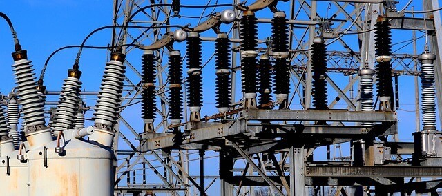
DATA ON SUB-STATIONS
1. Sub-Station Operational concepts:-
a. Equi-Potential Concept :- This concept is an important tool for the power system for the operation of Isolator (air break switch). The terminals in the system need to be connected by isolator are charged to the same potential. Then the isolator /air break switch is operated smoothly with out developing spark in the system.
b. Dead Line Charging :- Charging or electrification of any bus/line from zero potential is called dead line charging. Generally this charging does not get any involvement of current flow, but due to capacitive and inductive effect of the line/system, the charging current only flows.
c. Synchronization Charging :- In literal meaning, synchronization means a successful combination of two system. When two different systems are planned to be combined, the electrical parameters of both the systems should be alike or in phase. These parameters are 1. Voltage (Its magnitude, phase angle and sequence), 2. Frequency (Its magnitude). So to monitor the parameters, the synchroscope is used, that indicates the condition of synchronization and according to the limit of synchronization, the systems are allowed to be closed either manually or automatically. This facility of synchronization is generally available in generating station.
1. Idle Charging of Transformer: –
Energisation of any electromagnetic unit like transformer either from HV side or LV side can be called “Idle charging”. This charging is involved with the flow of magnetic inrush current. The magnitude of this current depends upon the following factors.
- Type of magnetic core used
- Saturation and back emf in the system
- Pattern of enersisation of the voltage wave form
- Residual flux in the transformer
2 . Power flow Calculation :-
Every operational engineer should have to know the fundamental idea for the calculation of power flow and current at different necessary parameters during the operational of the power system. power = √3 VI cosφ watt Following table would help the engineers for the calculation Thumb rule Current = (600 x MVA)/ KV Actual rule Current = (577 x MVA)/KV Where MVA = Rating of Transformer KV = Rated voltage of Transformer
| Supply Rated Voltage (KV) | Actual Current/MVA | Thumb Rule Current/MVA | Thumb Rule Current/MWatt (For cosφ = 0.9) |
| 11 | 52.45 | 54.55 | 60 |
| 33 | 17.48 | 18.2 | 20 |
| 66 | 8.74 | 9.1 | 10 |
| 132 | 4.37 | 4.55 | 5 |
| 220 | 2.6222 | 2.73 | 3 |
| 400 | 1.44 | 1.5 | 1.66 |
3 . Parallel Operation of Transformer : – For any power sub- station, different transformer are connected in parallel to cater load to common bus. Before keeping these units in parallel following conditions are to be satisfied.
Condition for parallel operation
- Same inherent phase angle difference between primary and secondary terminals.
- same frequency
- same phase rotation
- same voltage ratio
- same polarity
Also Read : ELECTRICAL FAULT FINDING


3 thoughts on “SUB-STATIONS”