
CURRENT TRANSFORMER (CT)
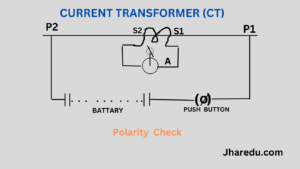
Polarity check Each CT should be individually tested to verify that primary and secondary polarity marking are correct. The ammeter should be center zero type. The connection arrangement of CT terminals, battery and ammeter is shown.
Show push button in closed – If should give a +ve flick.
Show push button is opened -ve flick.
This ensures correct polarity.
Ratio check.
Current is passed through primary and secondary and current is measured. The calculated ratio should match is the factory ratio.
Magnetization curve test.
Secondary winding is energized through a variable auto Transformer while the primary circuit is open, current and voltage are measured. Voltage is slowly raised while the magnetizing current is seen to rise very rapidy for a small increase in voltage. This indicates the approximate knee point or saturation flux level of the C.T.
The magnetizing current should then be recorded for several levels of applied voltage as the voltage is
reduced to zero.
Recommendations – Auto transformer of at least 8 amps rating be used when the current transformers tested
are rated at 5A secondary. Knee point is the point where 10% increase is applied voltage results in 50% increase in magnetizing current.
Insulation resistance Test
5 KV Megger for Primary
500 V-1000V megger for secondary IR value should be measured between primary to earth, primary to
secondary, secondary to earth.
POTENTIAL TRANSFORMER (PT)
Polarity Test – Same as described in case of CT. It if is a CVT then polarity of the transformer at the bottom of the
capacitor stack should be checked.
Ratio check – Apply LT voltage on primary, measure voltage at secondary. Calculate ratio. This should tally with
designed ratio.
IR test – IR should be measured between primary to earth, primary to secondary, secondary to earth. Remove conduct or jumpers from the CVT top terminal. Connect the HV terminal of the test kit.
Phasing Check : The secondary connections for a three voltage transformer or a bank of three voltage trans-
formers must be carefully checked
Measure secondary voltage between phases and neutral. Check the phase rotation which a phase rotation
meter. Provided existing proven VT is available on the same primary system and secondary earthing is em-
ployed. For phase to be correct, there should not be any voltage between R-R, Y-Y, B-B of secondary outputs.
Also Read : TESTING AND COMMISSIONING
Also Read : ELECTRICAL FAULT FINDING